|

 Up
Up
 1903 Propellers
(You are here.)

  Need
to Need
to
find your
bearings?
Try
these
navigation aids:
If
this is your first
visit, please stop by:
Something
to share?
Please:
|
|
Available in Française, Español, Português, Deutsch, Россию,
中文,
日本, and others.
 etting
out to make their first set of propellers in December 1903, the
Wright brothers were astounded to find there was no scientific basis
for propeller design. They had presumed that during the decades the
US. Navy had been using propellers, they would have developed some
mathematical theory for describing their performance. But the brothers
could find none -- the Navy's design method was simply "cut and try." etting
out to make their first set of propellers in December 1903, the
Wright brothers were astounded to find there was no scientific basis
for propeller design. They had presumed that during the decades the
US. Navy had been using propellers, they would have developed some
mathematical theory for describing their performance. But the brothers
could find none -- the Navy's design method was simply "cut and try."
Unwilling to leave this important process to chance, in January 1903 the Wrights built a
wind tunnel slightly larger than their 1901 tunnel and studied the
performance of 28-inch long propeller designs, developing their own
theory. Wilbur took the lead in this work as he had in their earlier
wind tunnel investigations. Possibly the most important discovery
that he made during these experiments was that a propeller was a wing traveling in a spiral
course. As such, it developed lift in a horizontal direction. This force,
combined with the reaction to the displacement of the air, was
thrust.
By February 1903 the brothers felt they had a firm grasp of
how a propeller worked. Wilbur designed and carved his first
full-size set of propellers -- 102 inches (2.6 meters) long,
tapering from 6 inches at the tip to two inches at the hub (15.2 cm
to 5 cm). Wilbur had determined he and Orv would need 90 pounds of
thrust to sustain the Flyer in flight at 24 mph (38.6 kph). When
tested at 245 rpm, the props fell short of the mark. Wilbur
determined that the reason was that the propeller pitch (the angle
at which the blade met the air) was too steep. In March, he began
designing an improved prop and by June 1903 he had carved two of
them -- one to turn clockwise on the right side of the Flyer and the
other to turn counterclockwise on the left. These counter-rotating
props would cancel the effects of any propeller torque that might
have otherwise pulled the Flyer to the left or right as it flew.
The new props were made from three laminated (glued face-to-face)
spruce boards. They were the same length at the first test prop, but
wider at the tip -- 8 inches (20.3 cm). Will had also adjusted the
pitch. The brothers had no opportunity to test the props at this
time -- they were consumed by other problems. But they were
confident of their work. When the brothers finally did get a chance
to test these propellers on the fully assembled Flyer at Kitty Hawk,
they found they produced a combined thrust of between 120 and 130
pounds at 330 rpm. They were also remarkably efficient, converting
66 percent of the mechanical energy from the motor into thrust.
References:
- Lippincott, Harvey H. Propulsion System of the Wright Brothers. In Wolko, Howard
S. (editor), The Wright Flyer, an Engineering Perspective. The Smithsonian Institution
Press, 1987, pp 79-82.
- McFarland, Marvin W. (ed) The papers of Wilbur and Orville Wright. McGraw-Hill Book
Co., New York, 1953, pp 1210-1214.
[Submitted by Joe W. McDaniel]
|
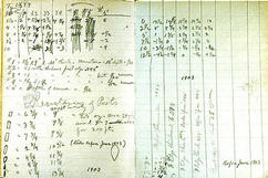
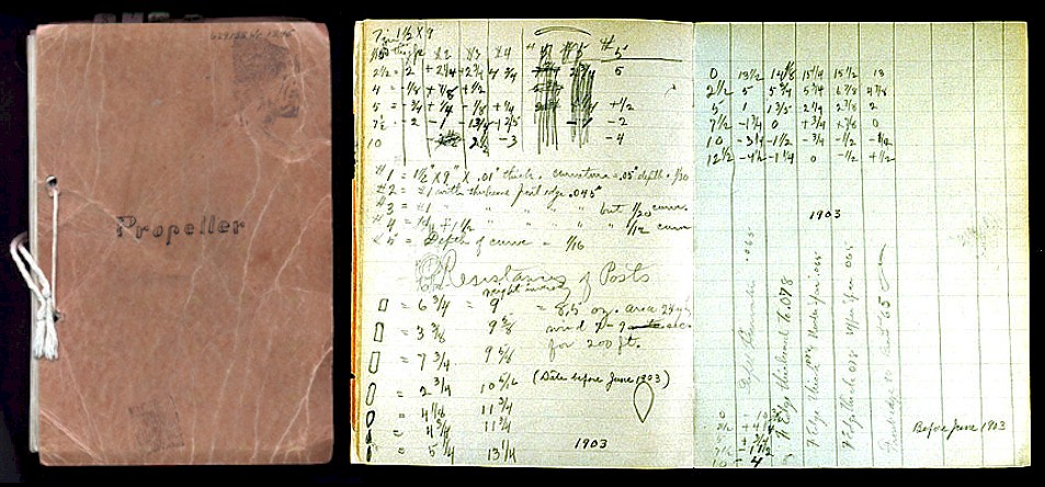
In early 1903, before designing their airplane propellers, the
Wrights first conducted wind tunnel experiments to determine how
propellers worked. These are some of the notes from their tests.
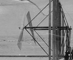
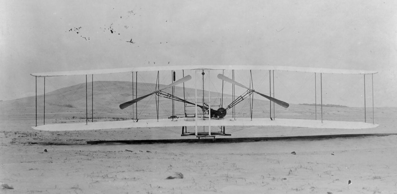
A side view of the 1903 propellers mounted on the Flyer in Kitty
Hawk. These were carved by hand from
laminated layers of spruce. The thin tips were covered with canvas to keep them from
splitting.
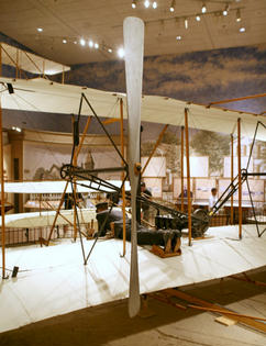
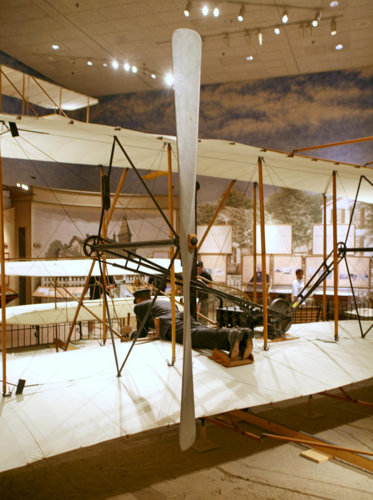
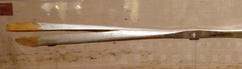
The propellers on the 1903 Wright Flyer in the Smithsonian Air &
Space Museum.
|
One of the most important conclusions the Wrights drew from their
experiments is that propellers are wings that revolve in circles and
produce lift. This propeller lift, however, is horizontal and
becomes thrust.
Like wings, propeller blades should be curved or cambered -- the
camber increases the amount of thrust produced.
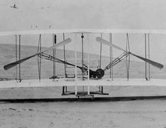
A rear view of the same props. Note that the chain drive on the left
is crossed -- the left propeller revolves counterclockwise while the
right revolves clockwise. The sideways torque generated by each prop
cancels out the other. Two props spinning in the same direction
would have given the Flyer a tendency to turn.
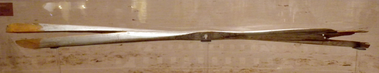
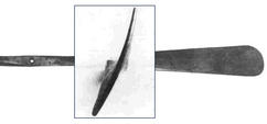
The props on the restored Flyer at the Smithsonian are not the
originals. These were damaged when the wind overturned the Flyer
after the fourth flight on 17 December 1903. The Smithsonian
displays one of the damaged original propellers separately from the
Flyer.
|