|

 Up
Up
 1903 Engine
(You are here.)

  Need
to Need
to
find your
bearings?
Try
these
navigation aids:
If
this is your first
visit, please stop by:
Something
to share?
Please:
|
|
Available in Française, Español, Português, Deutsch, Россию,
中文,
日本, and others.
 nce
they had decided to attempt powered flight, the
Wrights calculated they needed an engine that produced at least 8 horsepower
and weighed no more than 200 pounds (91 kilograms). A quick survey
of the automotive market showed there was no such engine available
and they would have to make their own. An acquaintance at the nearby
Buckeye Irons and Brass Works advised then that they could save
weight if they cast the engine block from aluminum. Although this
was a soft metal, alloys had recently been developed that were much
stronger – both Benz and Daimler
in Germany were successfully making engines with aluminum blocks.
The Wrights decided to cast the block from an alloy of 92% aluminum
and 8% copper. nce
they had decided to attempt powered flight, the
Wrights calculated they needed an engine that produced at least 8 horsepower
and weighed no more than 200 pounds (91 kilograms). A quick survey
of the automotive market showed there was no such engine available
and they would have to make their own. An acquaintance at the nearby
Buckeye Irons and Brass Works advised then that they could save
weight if they cast the engine block from aluminum. Although this
was a soft metal, alloys had recently been developed that were much
stronger – both Benz and Daimler
in Germany were successfully making engines with aluminum blocks.
The Wrights decided to cast the block from an alloy of 92% aluminum
and 8% copper.
After the castings had been made the Wrights "mechanician,"
Charlie Taylor, machined the parts and assembled the engine. He
later described his work:
"We didn’t make any drawings. One of us would sketch out the part
we were talking about on a piece of scratch paper, and I’d spike the
sketch over my bench. It took me six weeks to make that engine. The
only metal-working machines we had were a lathe and a drill press,
run by belts from the stationary gas engine.
"The crankshaft was made out of a block of machine steel 6 by 31
inches and 1-5/8 inch thick. I traced the outline on the slab, then
drilled through with the drill press until I could knock out the
surplus pieces with a hammer and chisel. Then I put it in the lathe
and turned it down to size and smoothness.
"The body of the first engine was of cast aluminum and was bored
out on the lathe for independent cylinders. The pistons were cast
iron, and these were turned down and grooved for piston rings.
"The completed engine weighed 180 pounds and developed 12
horsepower at 1,025 revolutions per minute. [It actually produced
nearly 16 hp when it was first started, by this dropped to 12 hp as
the engine heated up.]
"...The fuel system was simple. A one-gallon fuel tank [it
actually held just 22 ounces] was
suspended from a wing strut, and the gasoline fed by gravity down a
tube to the engine. The fuel valve was an ordinary gaslight pet
cock. There was no carburetor as we know it today. The fuel was fed
into a shallow chamber in the manifold. Raw gas blended with air in
this chamber, which was next to the cylinders and heated up rather
quickly, this helping to vaporize the mixture. The engine was
started by priming each cylinder with a few drops of raw gas.
"The ignition was the make-and-break type. No spark plugs. The
spark was made by the opening and closing of two contact points
inside the combustion chamber. These were operated by shafts and
cams geared to the main camshaft. The ignition switch was an
ordinary single-throw knife switch we bought at the hardware store.
Dry batteries were used for starting the engine, and then we
switched onto a magneto bought from the Dayton Electric Company.
There was no battery on the plane.
"Several lengths of speaking tube, such as you find in apartment
houses, were used in the radiator.
Other features included a bicycle chain turned the camshaft which
operating the spark breaker arms and exhaust valves, but the
"automatic" intake valves were opened by suction. Having no
throttle, the motor only ran at full speed, tuned with a lever that
adjusted the camshaft timing. A splash system lubricated the
bearings and other moving parts in the crankcase, while a small
gear-driven oil pump supplied oil to a tube that that dripped into
the cylinders and onto the pistons.
The engine was first run on 12 February 1903. The very next day
it overheated and seized up on the bench during a test run. New
castings arrived from the foundry on 20 April 1903 and Charlie had
the engine rebuilt and ready to go by early June.
After powering the Flyer on four flights at Kitty Hawk on 17
December 1903, the engine was seriously damaged when wind overturned
the Flyer. Today, the original cast aluminum engine block is
displayed at the museum attached to the Wright Brothers Monument at Kitty Hawk,
NC. The
Wrights sent the crankshaft and flywheel to be displayed at the
Aero Club of America Exhibition of Aeronautical Apparatus in New
York in 1906, and the parts were never returned. The engine now
on display in the 1903 Wright Flyer at the Smithsonian Institution was
built in 1916 when Orville restored the Flyer for an exhibition at
the Massachusetts Institute of Technology. Orville used some original parts
(we don't know which or how many), but he made much of the engine anew.
Specifications:
- Cylinders: 4
- Stroke: 4 in (10.2 cm)
- Bore: 4 in (10.2 cm)
- Displacement: 201 in3 (3.3 l3)
- Horsepower:12
- Ignition: Make-and-brake powered by low-tension (10-volt)
magneto.
- Weight: 180 lbs (81.6 kg)
- Unique features: Aluminum block, no carburetor.
References:
- McFarland, Marvin W. (ed) The papers of Wilbur and Orville Wright. McGraw-Hill
Book Co., New York, 1953, pp 1210-1214, plates 225-226.
- Hobbs, Leonard S. The Wright Brothers' Engines and Their design. Washington, D.C.:
Smithsonian Institution Press, 1971, pp 9-28.
- Lippincott, Harvey H. Propulsion System of the Wright Brothers. In Wolko, Howard S.
(editor), The Wright Flyer, an Engineering Perspective. The Smithsonian Institution Press,
1987, pp 82-86.
[Submitted by Joe W. McDaniel]
|
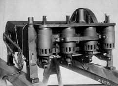
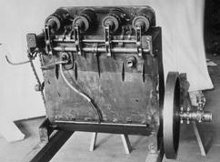
The 1903 Wright engine on a test bench after it was restored in
1916.
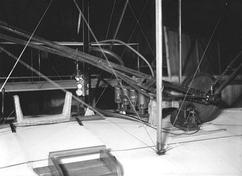
The 1903 engine mounted in the Wright Flyer during restoration.
As the engine heated up, the firing chambers on the left side of the
engine – nearest the
pilot – would glow red
hot.
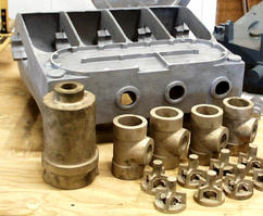
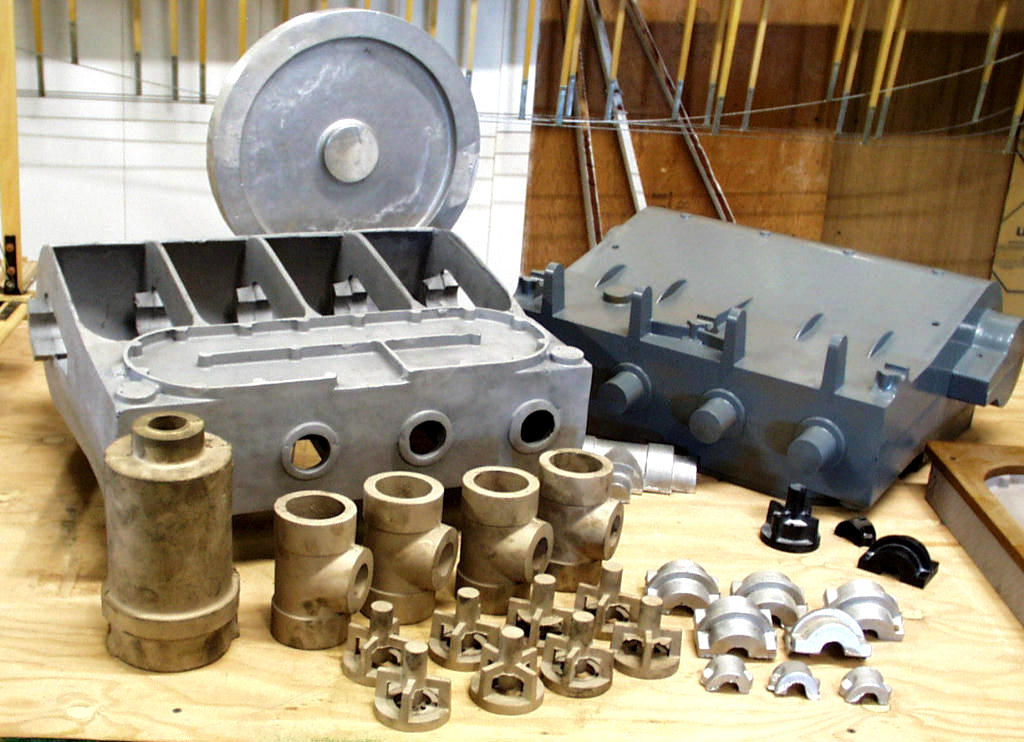
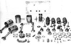
The castings for the 1903 Wright engine were made at the Buckeye Iron
and Brass Works, a nearby Dayton, Ohio foundry. The engine block and bearing
blocks were aluminum, the rest were cast iron.
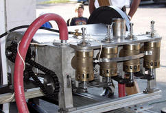
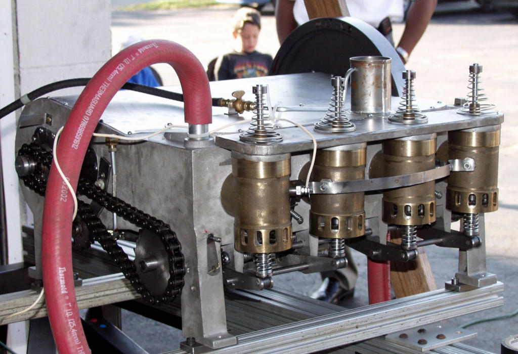
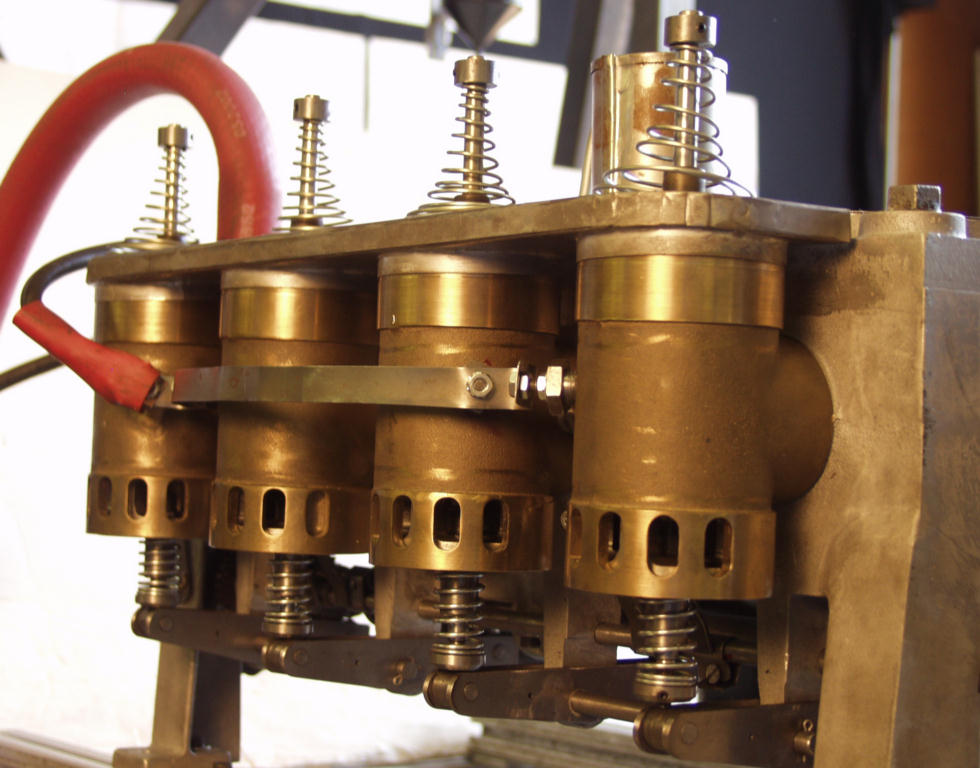
Our working replica of the Wright 1903 engine built by Terry Hesler.
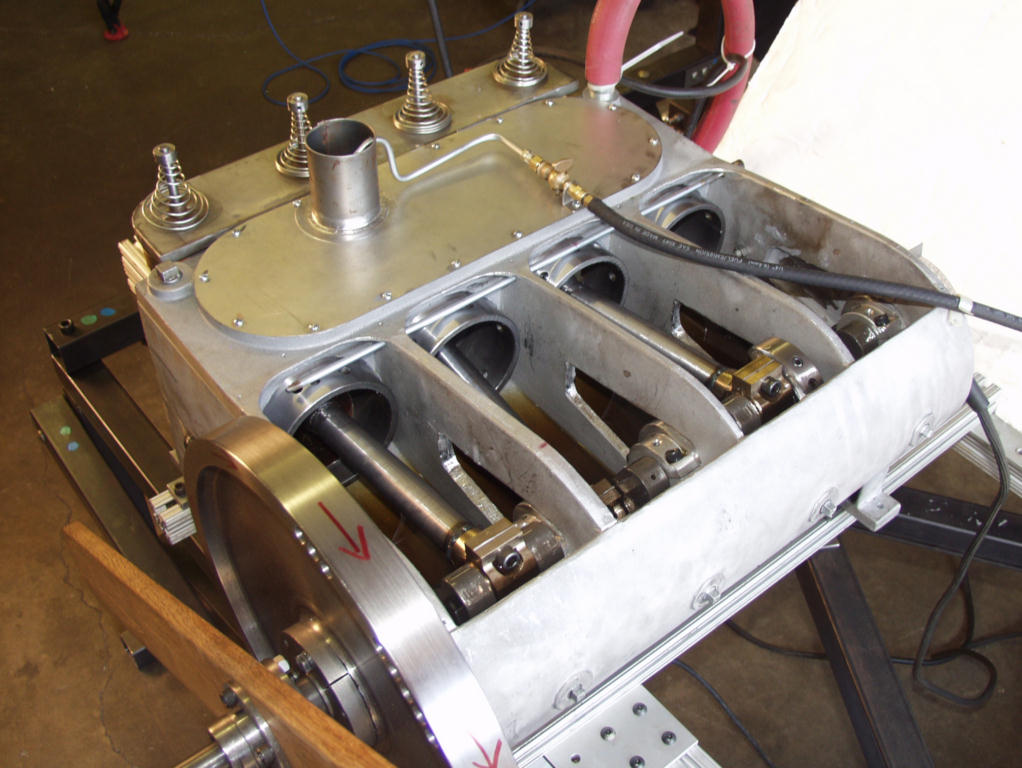
The 1903 Wright engine with the crankcase cover removed.
The spark that ignited the gasoline was supplied by a set of
electrical "points" inside each cylinder. The steel arms of the
points tipped with tiny amounts of platinum to forestall corrosion.
As the engine runs, the points momentarily close, making an
electrical connection, and then open again breaking the connection
and creating a spark. This was called a "make-and-break" ignition
system.

The fuel ignition doesn't happen in the cylinders, as in most
internal combustion engines, but in these combustion chambers. The
spring-operated "automatic" intake valves are at the tops of the
chambers, while the cam-operated exhaust valves are at the bottom.
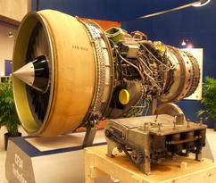
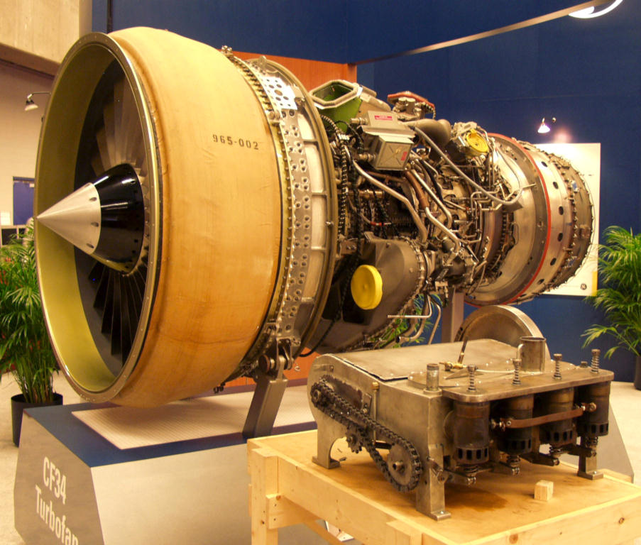
One hundred years of engineering advances separate these two
aircraft engines. The 1903 Wright engine, when coupled to the
propellers, produced 90 pounds of thrust (flb). The most recent
General Electric CF34 Turbofan jet engine generates well over 20,000
flb.
|
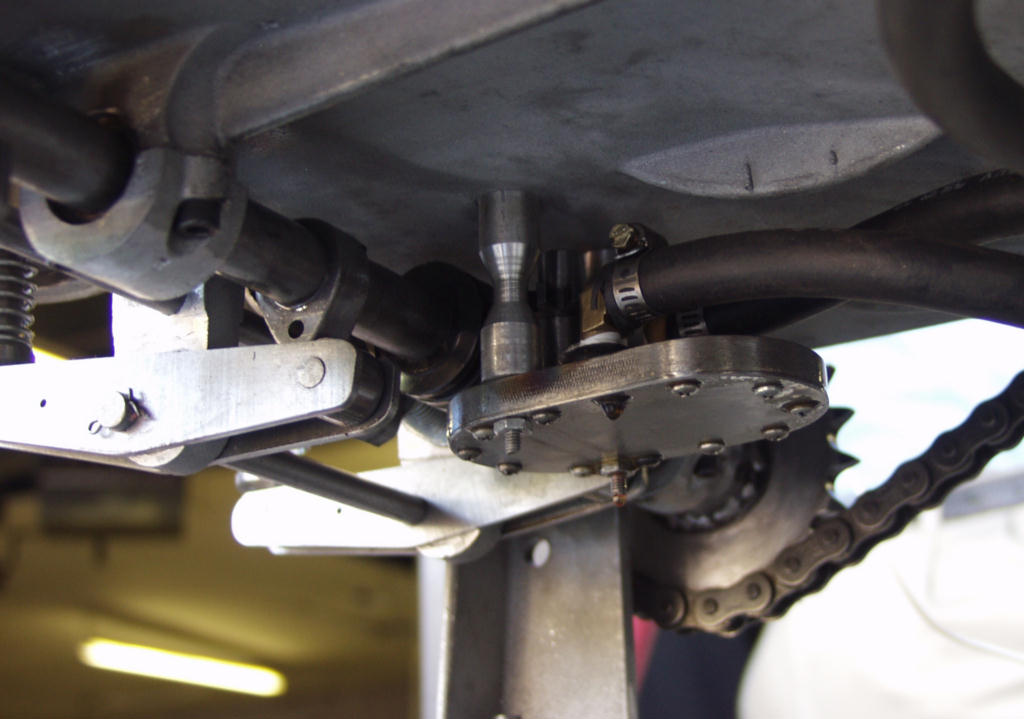
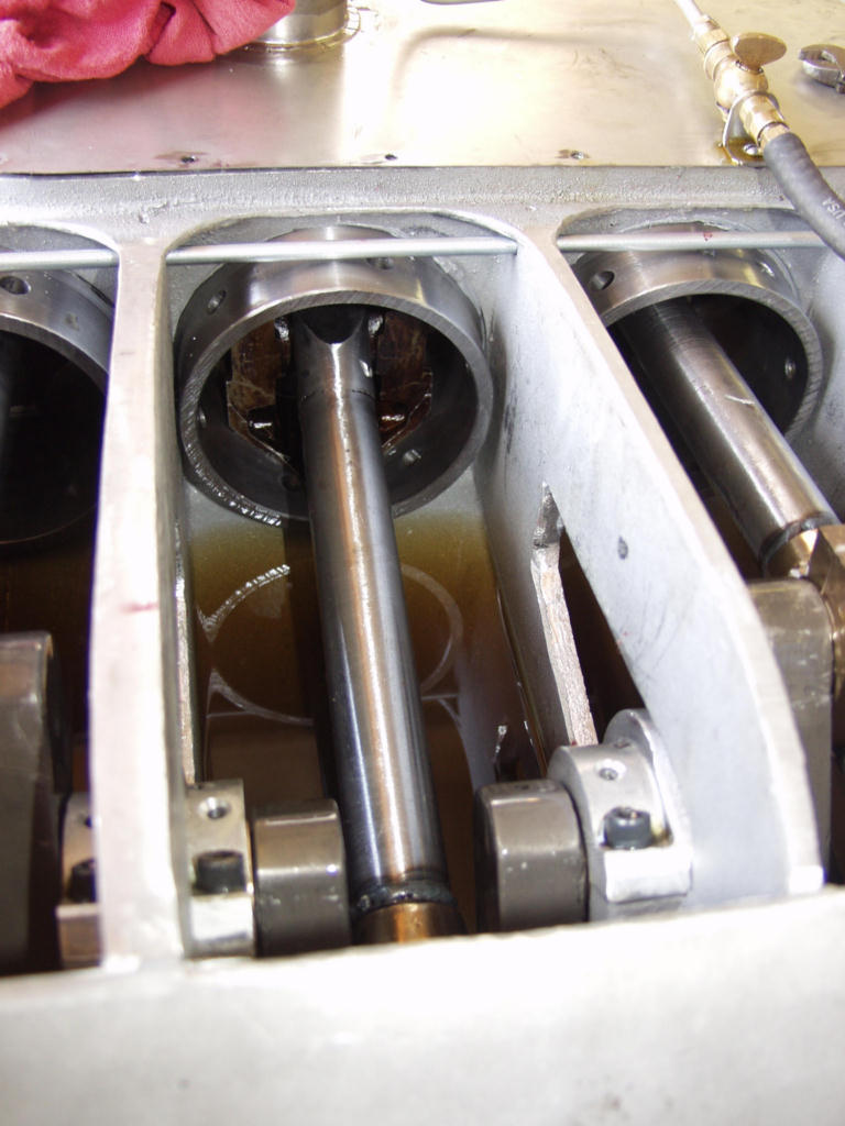
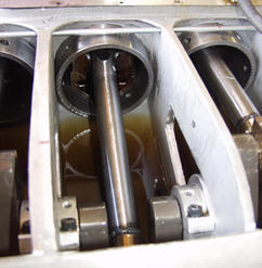
The underside of the 1903 Wright engine, showing the oil pump as
well as the cam shaft and rocker arms that operate the exhaust
valves.
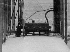
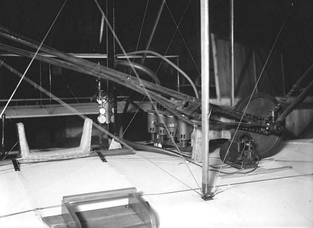
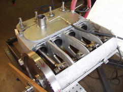
1903 engine installed in the Flyer at Kitty Hawk, before it flew. We're
looking at the right side, opposite the pilot.
Charlie Taylor machined most of the parts of the 1903 Wright
engine either from the castings or solid steel. A few, such as the
gears, were farmed out to the Garrison Machinery Works, just a few
blocks from the Wright bicycle shop.
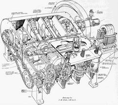
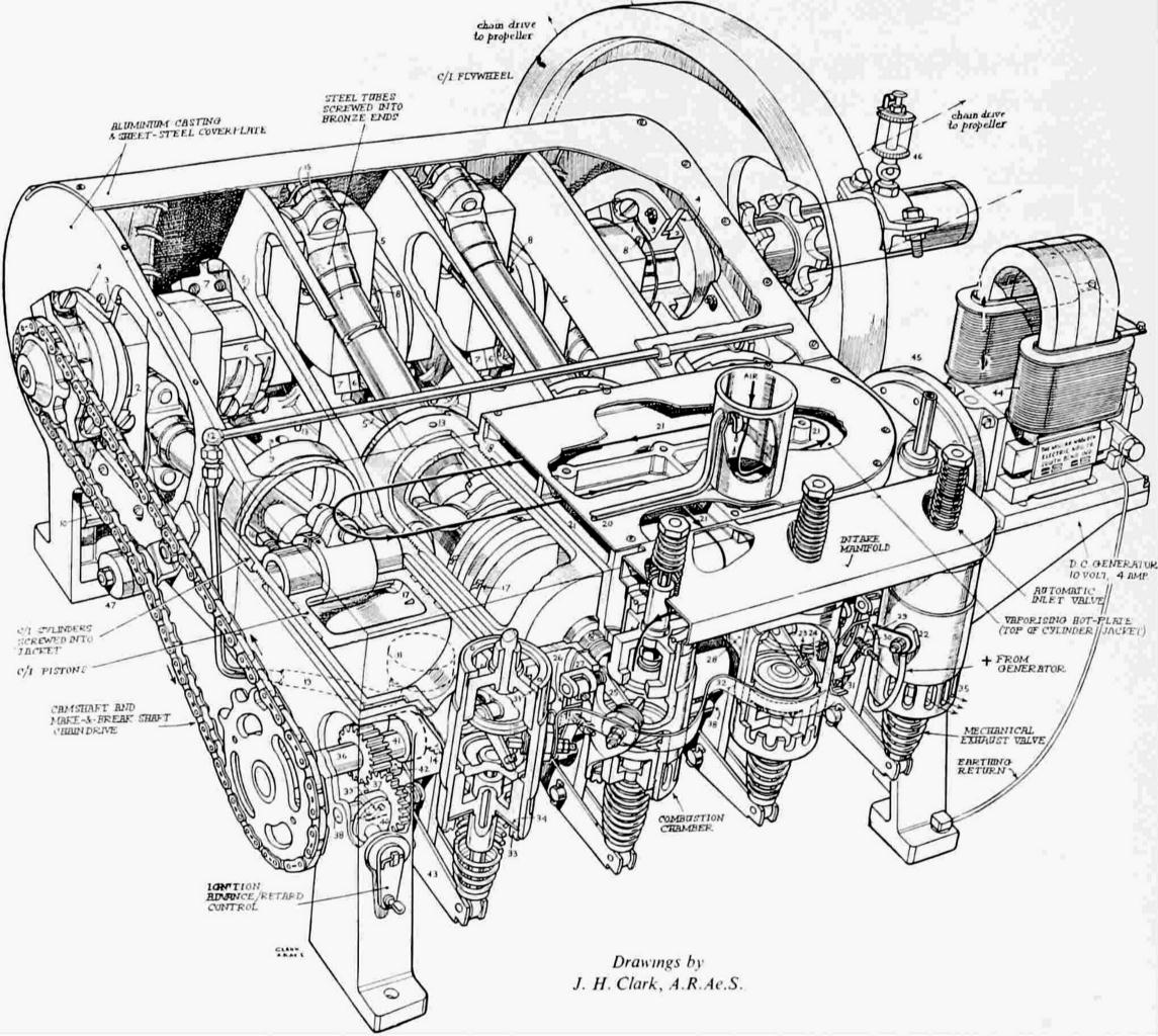
A cutaway drawing of the 1903 engine, showing the assembled parts.
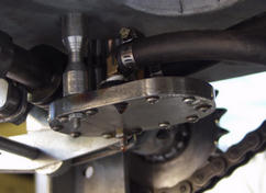
Most of the engine lubrication was "splash-and-dash" -- the
crankshaft churned the oil creating an oily vapor inside the
crankcase. This small oil pump delivered extra lubrication to the
pistons.
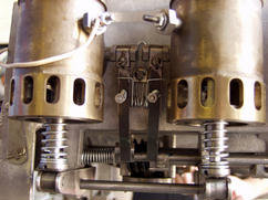
A detail showing the mechanism that opens and closes the points.
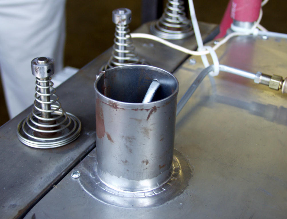
The 1903 Wight engine had no carburetor to vaporize the fuel.
Instead, gasoline dripped onto the hot engine block through this
opening. As the gasoline evaporated, it was sucked into the
combustion chambers.
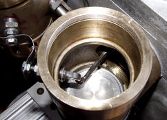
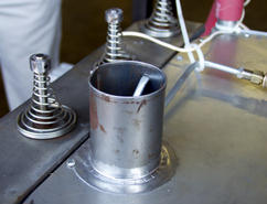
A detail showing a piston in its cast-iron cylinder. The cylinder is
mounted in the aluminum engine block. The tube above the cylinder
drips oil onto the interior surface of the cylinder where it is
picked up and distributed by the piston rings.
|