or
an airplane to successfully take off, it must first achieve minimum
flying speed. This is the air speed where: or
an airplane to successfully take off, it must first achieve minimum
flying speed. This is the air speed where:
- The air flows over the wings fast enough to develop sufficient
lift to support the weight of the airplane, including its pilot,
passengers, cargo, and fuel.
- The air flows over the control surfaces fast enough to make them
effective and allow the pilot to balance
and navigate the airplane as it flies.
For the Wright brothers in 1904, minimum flying speed was 27 to 28
miles per hour (45 kph). This was the speed needed to get the Wright
Flyer II into the air and keep it there. Unfortunately, this was not
an easy speed to attain at Huffman Prairie. While they were at Kitty
Hawk in 1903, the Wright brothers had performed an experiment that
revealed what sort of speed they could achieve during a take-off with
the 135-pound thrust of the propellers alone. From a standing start at
the beginning of their launch rail, the Flyer gained a forward speed of
6 miles per hour (9.6 kph) after traveling 80 feet (24 meters). Higher
speed would require a longer a longer take-off roll. That, of course,
required a longer launch rail – and 80 feet was all they had. The brothers
compensated by waiting for a high wind. On 17 December 1903, the wind
speed plus the speed they gained rolling along the launch rail was
enough to get them flying.
But there rarely was enough wind to do this at Huffman Prairie.
During the summer months, the average wind speed for the Dayton area is
just 7 to 9 miles per hour (11 to 14 kph). If the ground had been
smooth, they could have discarded the launch rail and mounted the
Flyer II on wheels – this would have allowed them a take-off roll as
long as the flying field. But Huffman Prairie was covered with small
hills or "hummocks" about 6 inches (15 centimeters) high in all
directions, probably due to the hummock sedge that grew there. Wheels were useless. So the Wright brothers began laying
more and more track, sometimes extending the launch rail over 250 feet
(72 meters) long.
This proved impractical. The launch rail had to be laid parallel to
the wind, and the wind came from a new direction every day. Even if they
could have achieved minimum flying speed without using the wind, a cross
wind might tip the Flyer off the rail before it had enough speed for the
controls to become effective. This meant the brothers had to lay the
track anew every time they attempted a take-off. This task took hours,
and oftentimes the wind direction changed before they finished laying
the rail.
In late August of 1904 they began to consider using a catapult to
fling the Flyer into the air. The idea may have been suggested to them
by their friend, Octave Chanute. As they were attempting to fly at
Huffman Prairie, Chanute was getting ready to exhibit one of his gliders
at the 1904 Louisiana Purchase Exposition in St. Louis. He rigged a 10
hp electric motor and a long rope to tow the aircraft into the air.
Instead of using a motor, the Wrights decided to pull the Flyer along the
rail with a falling weight . As weight fell, it would naturally
accelerate due to the force of gravity. This would pull the Flyer faster
and faster until it (hopefully) reached flying speed.
The brothers acquired a metal tower 20 feet (6 meters) high, probably
salvaged from an old wind mill. They also found seven cast iron weights,
each weighing 200 pounds (91 kilograms). Most likely, the weights
once served to counterbalance a freight elevator. The Wrights placed the
tower near the hangar where they would begin their take-off roll. On
days when the brothers flew, they would lay the launch rail extending
out from the tower. There is some thought that the tower may have been
mounted on skids so that it could be turned as the wind direction
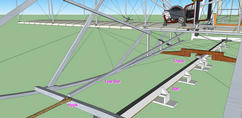
changed. A rope ran from the tower to a point about 65 feet (20 meters) along the
launch rail, looped over a pulley on the side of the rail, and ran back
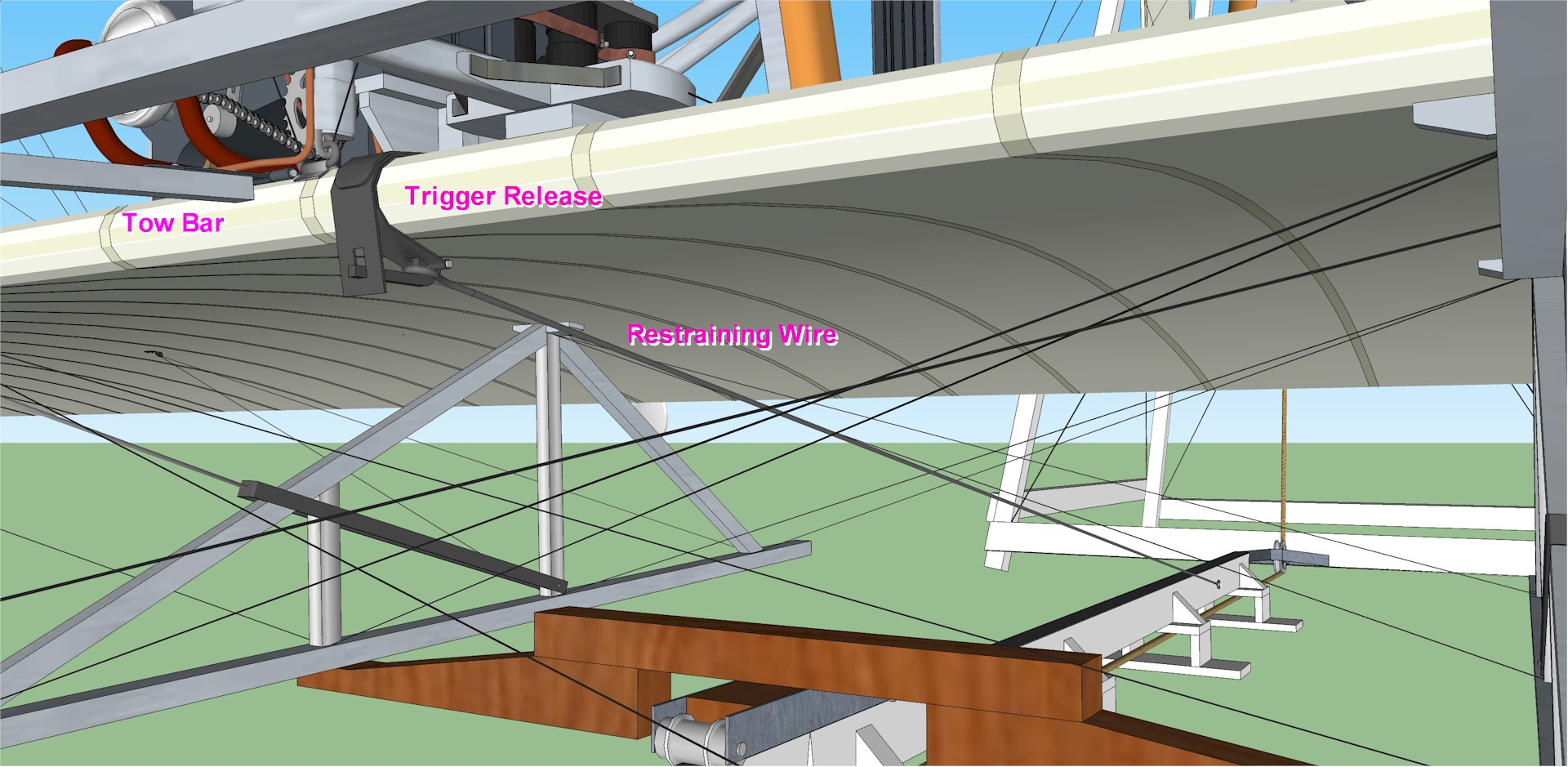
to the Flyer. The Wrights tied an "eye splice" in this end of the rope,
forming a loop that slipped over a hook at the end of a "tow bar" – a long
stick hinged to the leading edge of
the Flyer's lower wing.
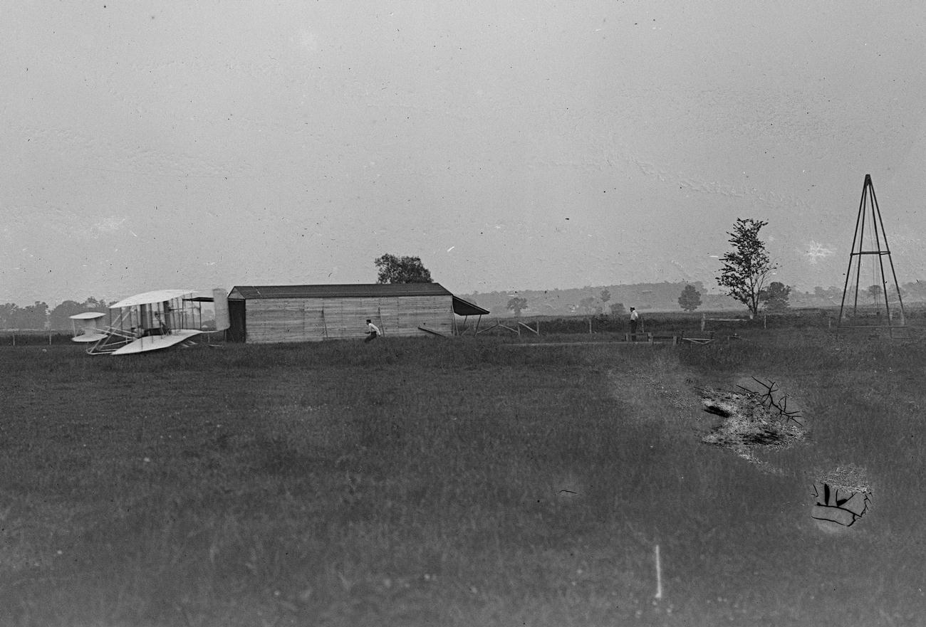
The other end of the rope ran under the Flyer, through a pulley at
the front of the tower (the "base pulley" on the illustration), and up to a double pulley at the
tower's top. From the
double pulley, the rope ran down and through a single pulley attached to
the stack of iron weights, up through the double pulley again, and back
down to the weights, so it appeared as if there were three lengths of
rope supporting the weights. In this way, the pulley system was leveraged three
to one – for every foot that the weights fell, the rope would pull the
Flyer three feet along the rail. From the top of the tower, the weights
fell a little over 16 feet (5 meters) before they struck the ground, so
the rope pulled the Flyer for the first 50 feet (15 meters) that it traveled along
the rail during its take-off run. This same system also reduced
the pull on the rope by a factor of three. If the Wrights used all seven
weights (1400 pounds or 635 kilograms), the rope would pull the Flyer
with a continuous force of 466 pounds (634 newtons) until the weights
hit the ground.
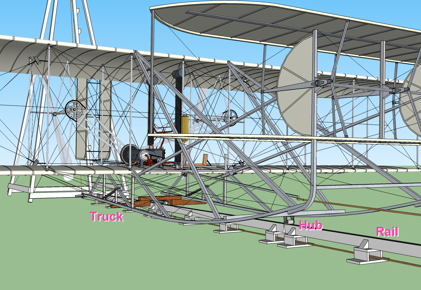
The Wrights completed the catapult and used it for the first time on
7 September 1904. Before cocking the catapult, the Wrights first placed
the Flyer so its skids rested on a carriage or "truck" designed to
roll along the launch rail. They rolled the Flyer and the truck as close
as possible to the beginning of the rail and attached a restraint – a
wire or iron rod that ran up from a stake at the end of the rail to a
trigger-release mechanism on the leading edge of the Flyer wing, right
next to where the tow bar was attached. (This trigger release may have
also been suggested by Chanute.) This kept the Flyer from being pulled
forward until the pilot was ready to fly. The Wrights then pulled on the
looped end of the rope, hauling the weights up to the top of the tower.
They may have borrowed one of the draft horses that were pastured in the
Prairie to help do this. When weights reached the top, they hooked the
rope to the tow bar and let the weights settle a few inches.
The rope, tow bar, and restraining wire were now taut, straining under
hundreds of pounds of tension.
The pilot climbed aboard the Flyer. The engine was started and
allowed to warm up for a few moments. When the engine was running
smoothly and the pilot had screwed up his courage, he reached down and
pulled the trigger release. A small level snapped down, releasing the
restraining wire. The Flyer began to roll forward on the launch rail,
accelerating as the weight fell from the top of the tower. When the
Flyer passed the rail pulley, the looped end of the
rope slipped off the hook at the end of the tow bar. By now, the Flyer
was moving fast enough through the air that the controls were effective. The pilot kept the wings level and the nose
down so the Flyer remained on the rail, continuing to accelerate for
another 50 to 60 feet (15 to 18 meters). Meanwhile, the wings seemed to
fill with air and the Flyer began to dance as lift increased. As pilot and flying machine
reached the end of the rail, the pilot pulled up slightly on the
elevator, the nose of the airplane rose, and the Flyer leaped into the
air.
|

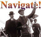
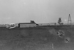
Only one photo exists that shows the catapult in 1904. It can barely be
distinguished in this long shot of a flight on 16 October.
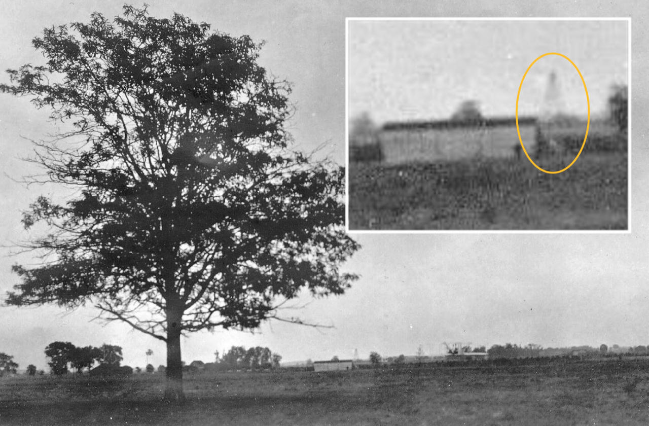
The only photo that shows the original catapult in any detail is this one from 24
June 1905. The Wrights have just launched the 1905 Wright Flyer III in
its first incarnation, a few weeks before the aircraft crashed and had to be
rebuilt.
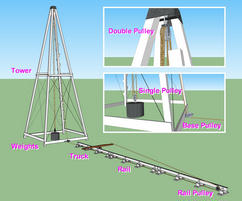
The launching apparatus that the Wrights used to get their early Flyers
into the air at first consisted of a monorail and a carriage or "truck."
The rail provided a long, smooth surface for the take-off roll, and the
truck supported the Flyer while it rolled along the rail. In late 1904,
the brothers added a "catapult," consisting of a stack of iron weights,
a tower from which to drop the weights, a long rope to pull the Flyer
along the rail as the weights dropped, and several pulleys through which
the rope passed.
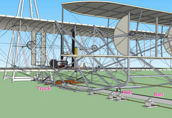
To use the catapult, the Wrights placed the Flyer on the rail so the
main skids rested on the truck. The bicycle hub that was attached to the
crossbar on front skids rested directly on the rail.
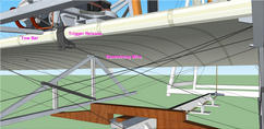
The brothers rolled the Flyer back to the beginning of the rail (close
to the tower) and attached a restraining wire to a trigger-release on
the front edge of the lower wing. The restraining wire was originally
anchored to a stake, but after the stake pulled out of the ground on 1
November 1904, the Wrights decided to anchor it to the rail.
With the Flyer restrained from rolling forward, they hauled the weight
to the top of the tower and attached the rope to a hook at the end of a
tow bar.
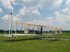
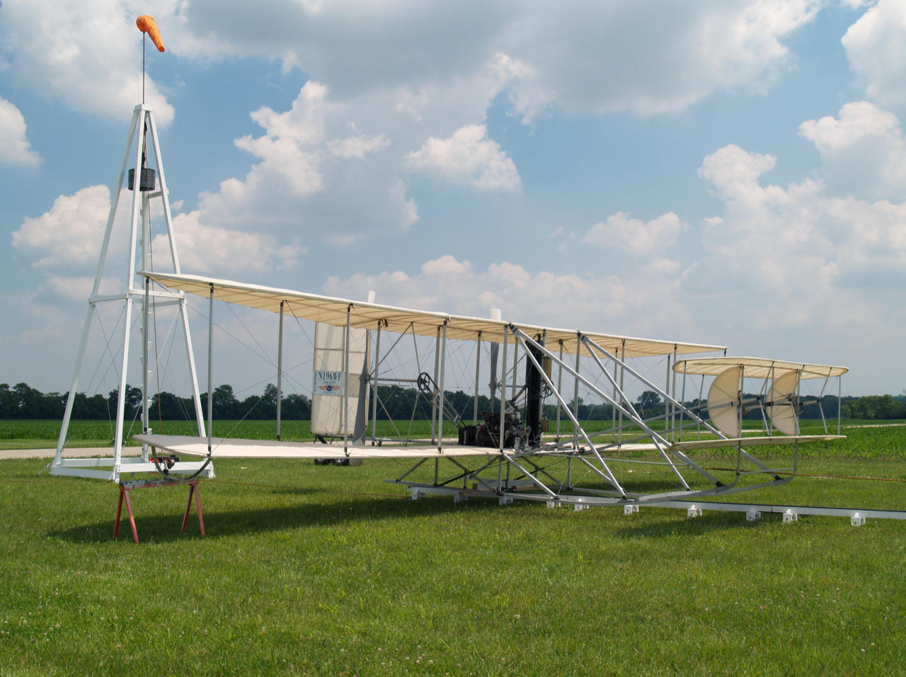
With the weight at the top of the tower and the Flyer restrained, the
catapult is "cocked" and the Flyer ready for take-off. This is
our replica of the 1905 Wright Flyer
III and the Wright catapult.
|
A
Virtual Walk-Around
- The Wright Catapult
in 3D is a digital model in a 3D-PDF file. This allows you
to view the model and zoom, pan, slide, and turn it to see the
catapult from any angle, close up or far away. The model shows the
1905 Wright Flyer III ready for take-off.
Important Note: You must have Adobe Reader 9.0
or later to view this model. If you don't already have a
copy of Adobe Reader or want to update your software, you can
download the latest version for free by clicking HERE.
Once you have an up-to-date Reader, simply click on the link to 3D
PDF file and it will load in a secure "protected view." Click
"Enable all features" (at the top right) and the 3D illustration
will appear with all the tools you
need to zoom, pan, slide, and turn the model. PDF readers other
than Adobe, including those that are built in to some browsers, may
not work.
|
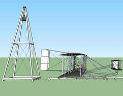
A side view of the Wright Flyer, launch rail, and catapult. To see
a 3D digital model of the catapult,
click HERE.
|